| O-Rings are one-piece molded objects made from elastometric seal with a circular cross-section. They are used to prevent fluid movement between mechanical parts by maintaining contact with the inner and outer walls enclosing the ring. The resiliency of the rubber provides a zero-pressure seal. When pressure is applied, the fluid forces the O-Rings across the groove and causes more deformation. This leads to the ring flow up to the fluid passage and seal it against leakage. O-Rings are an example of self-energize seals, meaning they relay pressure inside the container (or pipe) to give them the pressure necessary to form the seal. O-Rings are inserted into cavities called glands, and they are used in either axial or radial seal designs. An O-Ring is described by its inner diameter, its outer diameter, its material hardness (or durometer) and its material composition. Dimensions of O-Rings are given in ANSI/SAE AS568A. A seven-digit number is assigned to each ring to designate the ring size and their composition. The first three digits are standardized and they specify the ring size. However, different manufacturer use different system to specify the composition. For this reason, the ANSI/SAE AS568A only publishes the first three digits for dimension specification. When installed, an O-Ring compresses and deforms slightly into the free space within the grove to from a proper seal. The ring's cross-section is approximately 20 percent greater than the gland depth and the groove width is about 1.5 times larger than the ring's width. | |||||||||||||||||||||||||||||||||
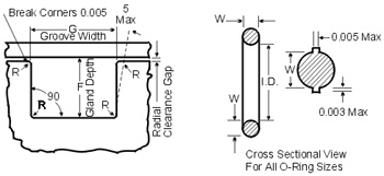 | |||||||||||||||||||||||||||||||||
Symbol Definitions | |||||||||||||||||||||||||||||||||
Parameters used in the discussion of O-Rings are defined in the following table:
| |||||||||||||||||||||||||||||||||
Radial Gland Symbol Definitions Parameters used in the discussion of glands for radial seals are defined in the following table:
| |||||||||||||||||||||||||||||||||
Design Guidelines Using the diametrical clearances given by the O-Rings' manufacturer usually provides the most effective and reliable sealing. They often provide information that can be used to estimate the gland depth required in O-Rings applications. This information is necessary for designing a system with a proper clearance gap so that the ring material will not extrude into the gap when subjected to pressure. The extruded ring material will quickly wear and fray, severely limiting the service life of the seal. Other factors, such as system pressure, ring compound and hardness, can affect the radial clearance used. There are number of ways to correct an extruding O-Rings application: | |||||||||||||||||||||||||||||||||
| |||||||||||||||||||||||||||||||||
| These modifications, however, have their drawbacks. For example, reducing system-operating pressure may affect the operational parameter of the system and harder O-Rings may result in higher friction and a greater tendency of the seal to leak at low pressure. In general, the ring's cross-section is about 20 percent great than the gland depth and the groove width is approximately 1.5 times the ring's cross sectional diameter if the its cross-section is larger than 1/16 in. The surface finish of the groove has a great impact on the performance of the seal. There are two things to consider for determining the surface finish roughness: | |||||||||||||||||||||||||||||||||
2. In the case of static seal, whether the seal is for a liquid system or a gaseous system. | |||||||||||||||||||||||||||||||||
The table below sums up the intended application with the proper surface finishes:
It is desirable to circumferentially stretch the O-Rings slightly so that it sits securely in the groove during assembly. This can be done by selecting an O-Ring with an internal diameter 2% to 3% smaller than the groove diameter. For Further Details Email us : sales@fitcoseals.com www.oringstore.com www.fitcoseals.com | |||||||||||||||||||||||||||||||||
Saturday, July 21, 2018
O-Rings Design Guidelines, Specifications - FITCO
Types of Oil Seal Materials / Material Selection Guide for Oil Seals - FITCO
Which is the Best Material for Your Oil Seal?
Application:
Radial shaft seals, also known
as lip seals, are used to seal rotary elements, such as a shaft or rotating
bore. Rotary shaft seals play a key role in extending the operating life of bearing systems and reducing the overall costs of maintaining these systems. The primary function of a rotary shaft seal is to retain bearing system lubricants therefore allowing the bearings to operate in optimal levels of lubrication. The secondary function of a rotary shaft seal is to exclude contaminants from the system, contaminants that can both damage bearings and break down the effectiveness of lubricants.
USP:
The seal construction will consist of a
sprung main sealing lip which has a point contact with the shaft. The point
contact is formed by two angles, with the air side angle usually less than the
oil side angle. “Depending on the seal type these two angles are varied to
create a “pressure distribution”
at the seal contact point which has a steeper slope on the oil side of the
seal. “The shallower the slope on the oil
side of the seal the wetter the seal will run”
An oil seal
normally consists of three basic components: Sealing Element, Metal Case, and
Spring. The function of an oil seal is to prevent leakage along the shaft. This
is mainly achieved by the sealing element. Materials normally used are Nitrile,
Acrylic, Silicone, and Viton Rubber.
Fluorinated Rubber (VITON)
Fluorinated rubber is widely known under the DuPont trade name of Viton®. Temperature Ranging -30 to 200° C , It has the best resistance to chemicals, and superior performance to high temperatures. Though Viton® provides so many good prospects, it has the highest cost.
Nitrile Rubber (NBR)
NBR is most commonly used material. It has good heat resistance properties, good resistance to oils, salt solutions, hydraulic oils, and gasoline. Operation temperatures are recommended from -40 to 120° C. It also functions well in dry environments, but only for intermittent periods. The disadvantage is poor chemical resistance.
Silicone Rubber
Silicone compounds
operate effectively in a broad temperature range of -50 to 180° C. It is
unsurpassed in its resistance to heat and low temperatures. The high lubricant
absorbency of silicone minimizes friction and wear. It is usually used for
crank shaft seals. Silicone has poor hydrolysis resistance. It should not be
used in oxidized or hypoid oils.
Polyacrylate Rubber
Acrylic rubber has
better heat resistance than Nitrile. It is recommended for high surface speed
environments. The operation temperatures are recommended from -20° C to 150° C.
It should not be used with water or in temperatures below -20° C.
MATERIAL PERFORMANCE
O: Applicable | X: Applicable but must be observed | XX: Applicable in a limited amount of time | XXX: Not Applicable
MATERIAL CHEMICAL RESISTANCE
O: Applicable | X: Applicable but must be observed | XX: Applicable in a limited amount of time | XXX: Not Applicable
For Futher Details
Email us : sales@fitcoseals.com
www.fitcoseals.com
Wednesday, July 4, 2018
O-Rings Seals for Connector and Metal Tube Adapters Assemblies - FITCO
Tube
Assemblies - Hydraulics Hose and Hose Fittings
For over a decade, we are manufacturing O-Rings for
metal tube assemblies because of our precision
engineering and quality control practices, companies have used our O-Rings for tube assemblies in hydraulic fluid transfer, fuel
and oil, lubrication, fleet, automotive, and military applications.
O-Rings for
Fuel Injection Tubes
O-Rings are used in Fuel Injection Tubes are used
in large numbers in all kinds of diesel engines for automobiles, ships,
construction equipment, and agricultural machinery
O-Rings for CRDi Tubes & Hydraulic Tubes
Common Rail technology operates at
very high-pressure to achieve better air-fuel mixing and as a result, higher
engine efficiency. We offer a qualitative range of High Pressure Hydraulic
Tubes.
O-Rings for EGR & Bellows
EGR tube assembly carries unburnt gas
vapors from the exhaust manifold chambers to the intake manifold and is
reintroduced into the engine firing sequence
We expertise in O-Rings and work in
team to develop highly customized
O-Rings for tube assemblies for their OEM products.
FITCO works to ensure that every component and assembly we supply meets
our highest expectations for quality and performance. Our experienced team
leverages their thousands of hours of quality testing experience to closely
inspect and approve each and every product that passes through our facility,
ensuring that you receive products that enhance and empower your equipment.
As a quality-source supplier, Fitco Engineers Pvt
Ltd consolidates and simplifies the engineering, specification, and purchasing
processes for you. From the prototype stage to production, you can count on Fitco
expertise for the essential o-rings for fluid transfer systems of
your machinery.

O-Rings Applications:
·
Hydraulic
·
Air Conditioning and Refrigeration
·
Truck and Bus
·
Pneumatic
·
Cooling
O-ring Installation
Instructions & useful with O-ring seal connectors and adapters.
O-ring seal fittings are used for direct connection to
existing pipe thread or straight thread ports which have a smooth, flat surface
perpendicular to the threaded port. O-ring seal fittings provide leak-tight
sealing on both vacuum and high pressure systems. The standard Buna N O-ring is
completely contained in a precision groove, to prevent O-ring extrusion at high
pressure. The precision groove also provides a controlled squeeze for a
vacuum-tight seal.
Note:
When installing an O-ring port:
1. Hand-thread until the O-ring compresses on the port
end.
2. Snug the fitting to the port with a wrench to completely
compress the O-ring.
3. Always use a back-up wrench to hold the O-ring seal
fitting body, when connecting or
disconnecting a end.
For Further Details Contact
Email: sales@fitcoseals.com
www.fitcoseals.com
Subscribe to:
Comments (Atom)